The Graphical User Interface
VCAMS is a python library for creating complex models, but it also comes with VCAMS GUI which a graphical user interface (GUI) offering part of the library’s functionality in a simple and convenient manner. It also allows the parameters to be exported to a configuration file, and imported later for modification or re-creation of the models.
The GUI has is shipped as a single portable executable (.exe file) which contains the library and all of the dependencies. It is currently compiled only for Microsoft Windows, but can be easily built from the source code on most platforms.
It should be noted that the GUI only offers some of the library’s functionality. Extremely complex models still need the scripting interface.
The following sections describe the different parts of the GUI.
Structure of the GUI
The GUI consists of three main sections which are illustrated in Fig. 1. They are:
The Menu Bar contains a number of menus which allow the user fast access to the import/export and model creation functionalities and also software help.
The Page Selection Area contains tabs similar to those found in a binder notebook. Each page has a purpose and asks for the parameters needed for that purpose. The pages are in a logical order and must be filled in that order. They will be described in the following sections.
Page Contents: After a page is opened, its contents are shown. Some of the parameters have default values and some fields will depend on other parameters.
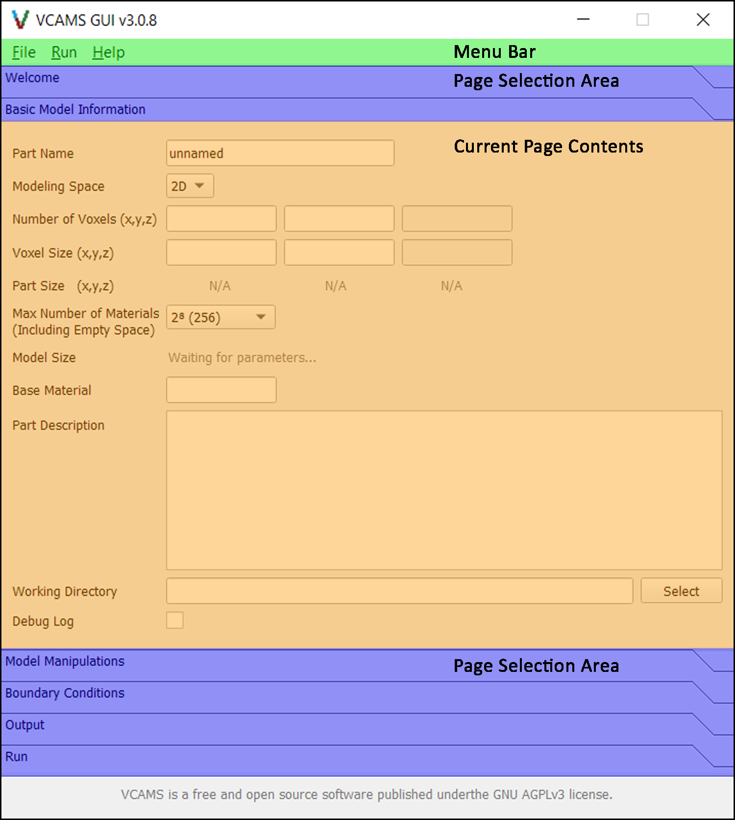
Fig. 1 Different sections of the VCAMS graphical user interface (GUI).
The Welcome Page
The welcome page simply shows a welcome screen and some information about the VCAMS software. It does not contain any model-related parameters or information.
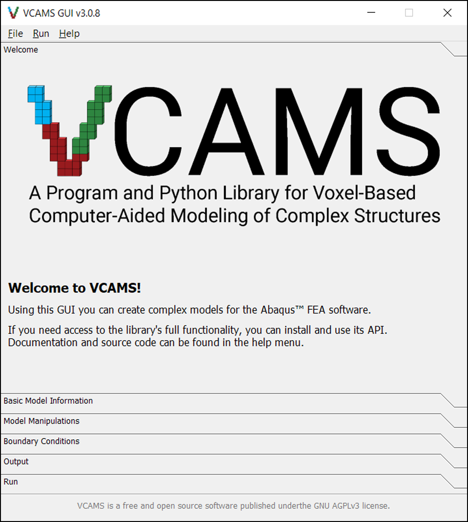
Fig. 2 The Welcome page of the VCAMS graphical user interface (GUI).
The Basic Model Information Page
This page (Fig. 3) asks for the information used for creating the base part.
These parameters are used to create a VoxelPart object
which is then manipulated and exported in the next sections.
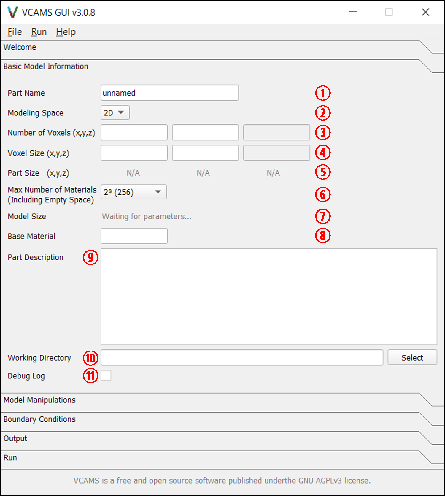
Fig. 3 The Basic Model Information page of the VCAMS graphical user interface (GUI).
The items numbered in Fig. 3 are as follows:
Part Name is used in a variety of places, including when exporting the part. It must be valid according to the documentation for the
vcams.helper.is_name_valid()function. The default value is “unnamed”.Modeling Space is the dimensionality of the output part which can be 2D or 3D. Some of the other features, such as modeling techniques, depend on this parameter.
Number of Voxels is an integer which determines the number of voxel elements. The third field will be disabled in the 2D mode.
Voxel Size is the actual size of a single voxel in each direction. The third field will be disabled in the 2D mode.
Part Size is the actual size of the resulting part if it was filled with elements. It is be automatically calculated by multiplying Number of Voxels and Voxel Size.
Max Number of Materials is an important parameter determining the number of material codes available for modeling. It is described in detail in the Materials section. The default value is usually enough for models created using the GUI.
Model Size shows the number of elements in the model and the amount of memory that is needed. It is be automatically based on Number of Voxels and Max Number of Materials.
Base Material is the material code assigned to all elements before any manipulation takes place. Users must make sure it is within the range specified by the Max Number of Materials parameter.
Part Description is a short description of the part which is used in a variety of places, including when exporting the part.
Working Directory is the path to a folder where the final results, temporary file, and log files will be stored. By default, it is set to a folder in the current user’s Desktop and the folder’s name is based on Part Name. It can also be changed using the Select button.
Debug Log determines if debug information should be written to the program logs.
The Model Manipulations Page
This page contains a select number of modeling techniques available in VCAMS. The page first asks the user to select a Modeling Mode and then shows the relevant form.
Different modeling modes are demonstrated in the Example Problems section.
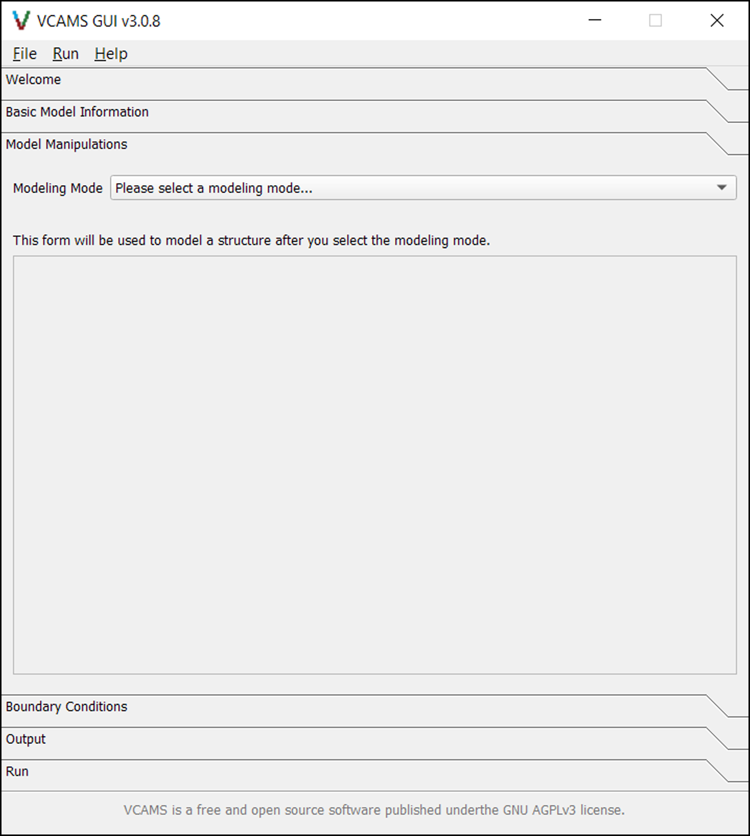
Fig. 4 The Model Manipulations page of the VCAMS graphical user interface (GUI).
The Boundary Conditions Page
This page contains four radio buttons which are used for choosing the boundary conditions that will be created as constraints on the model. They are described in the Boundary Conditions section.
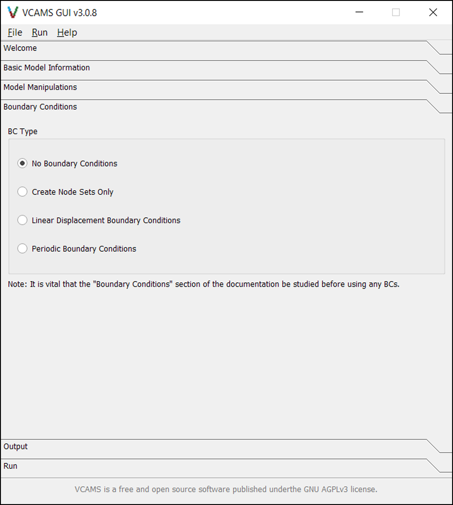
Fig. 5 The Boundary Conditions page of the VCAMS graphical user interface (GUI).
The Output Page
This page (Fig. 6) contains parameters used for exporting the model to Abaqus™.
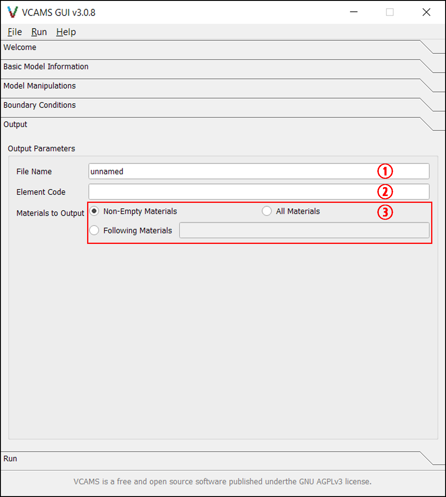
Fig. 6 The Output page of the VCAMS graphical user interface (GUI).
The items numbered in Fig. 6 are as follows:
File Name is the named given to the output .inp and .vcams files. This field automatically mirrors the Part Name field of the Basic Model Information page but can be changed to the desired name which must be valid according to the documentation for the
vcams.helper.is_name_valid()function.Element Code is an uppercase string denoting the element code assigned to all elements in the model. It must be a valid Abaqus element code such as CPE4R or C3D8R. This parameter is not validated so care should be taken regarding validity and compatibility. Currently, only 2D and 3D linear elements are supported by VCAMS. To get around this, you can convert to quadratic elements after importing the model to Abaqus™.
Materials to Output is a group of fields that select which materials are written to the output. The options are:
Non-Empty Materials which exports the elements containing every material code, except 0 which signifies empty space.
All Materials which exports all materials regardless of material code.
Following Materials which allows the user to enter a comma-separated list of material codes to be exported.
The Run Page
This page allows the user to finalize the process and see its progress.
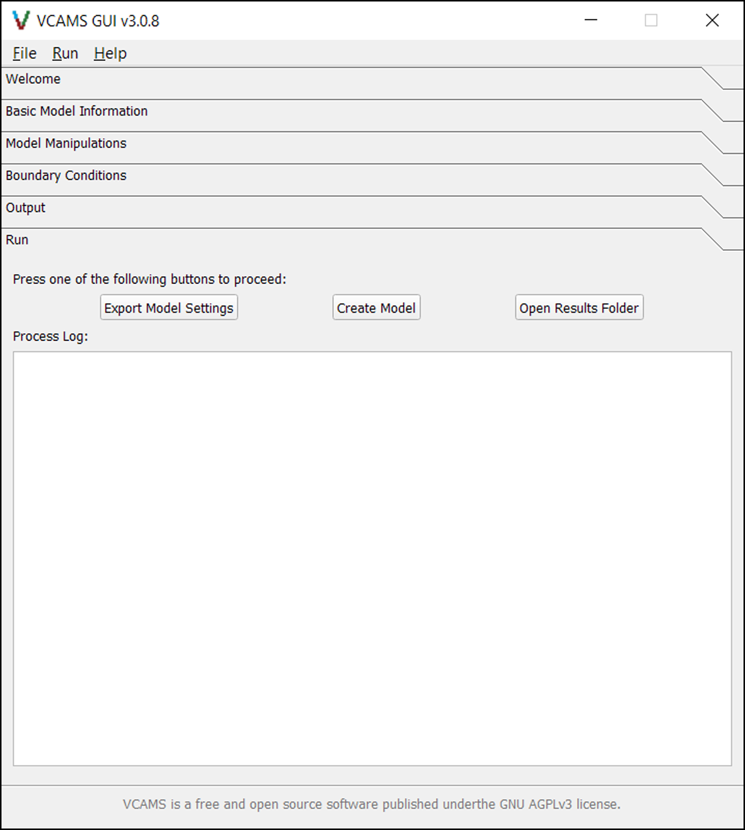
Fig. 7 The Run page of the VCAMS graphical user interface (GUI).
The items shown in Fig. 7 are as follows:
The Export Model Settings button exports the model parameters to a .vcams file which can be used for re-creating the current state of the GUI.
The Create Model button first exports the settings and then creates a model based on them.
The Open Results Folder button opens the directory in which the final models reside.
Process Log shows the progress of the current or last job. The verbosity of this log depends on the Debug Log checkbox of the Basic Model Information page.