Example G-2: Simple Filled 3D Part
In this example, the graphical user interface (GUI) is used to create a filled 3D part. This example mirrors Example A-2.
The structure is three dimensional with a shape of 50×75×100 voxels and has a base material of 1 and a voxel size of 0.02 units in all directions. The parameter log_debug is set to True for demonstration purposes.
The part is then exported to an Abaqus™ input file in 3D mode with C3D8R elements. The Non-Empty elements (which happens to be the whole model), are requested to be exported.
The following figures show the various tabs of the GUI in this example:
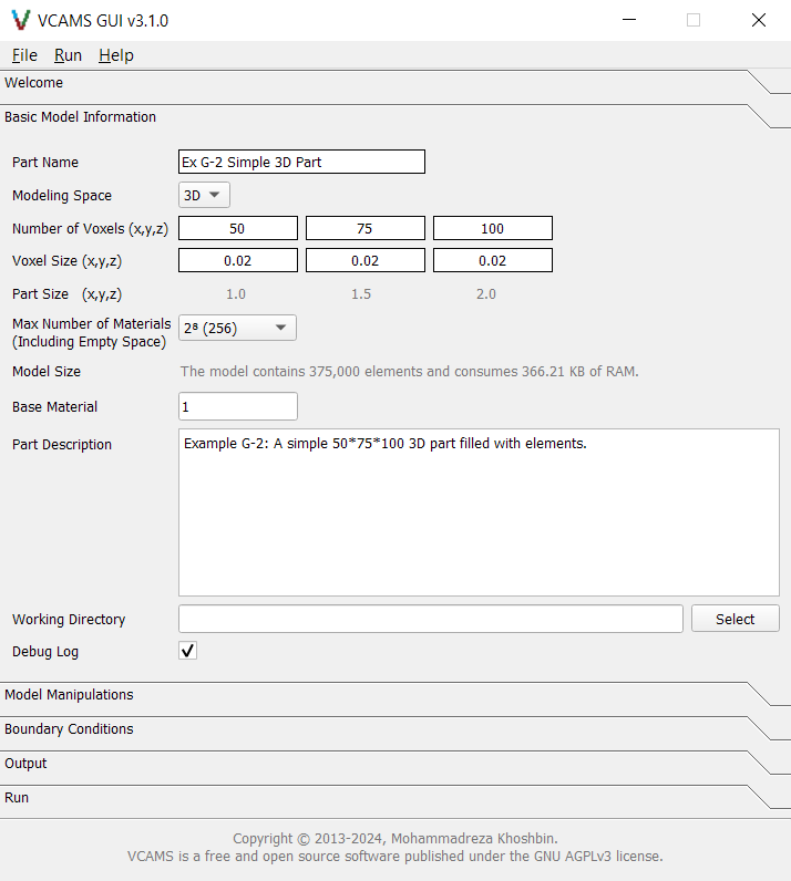
Fig. 33 The GUI’s “Basic Model Information” tab for Example G-2.
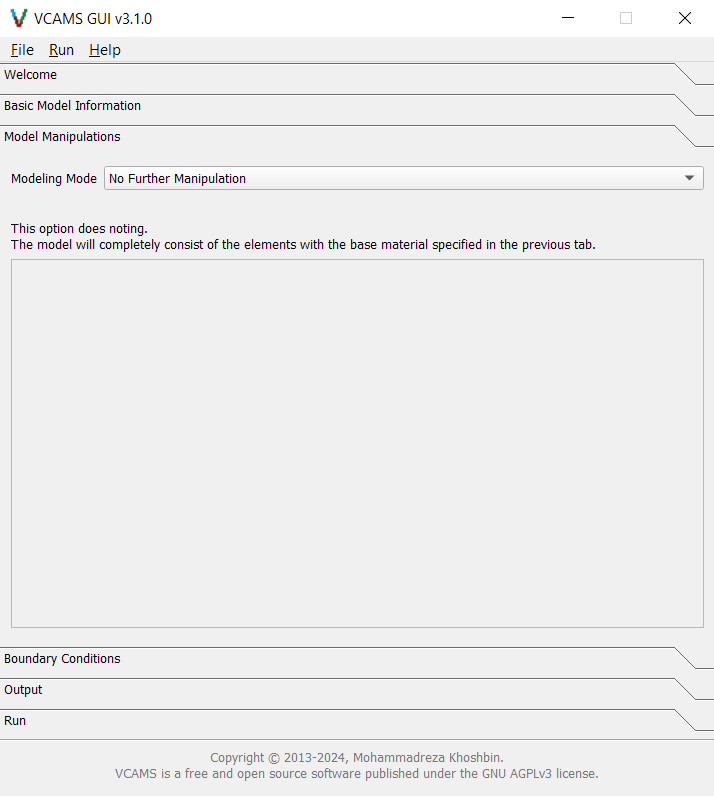
Fig. 34 The GUI’s “Model Manipulations” tab for Example G-2.
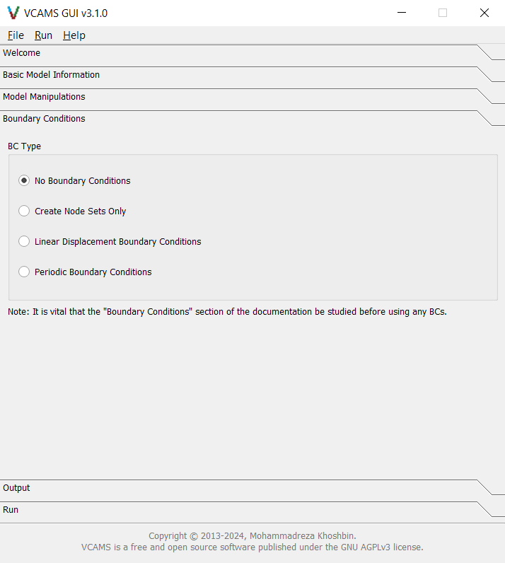
Fig. 35 The GUI’s “Boundary Conditions” tab for Example G-2.
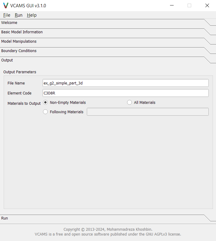
Fig. 36 The GUI’s “Output” tab for Example G-2.
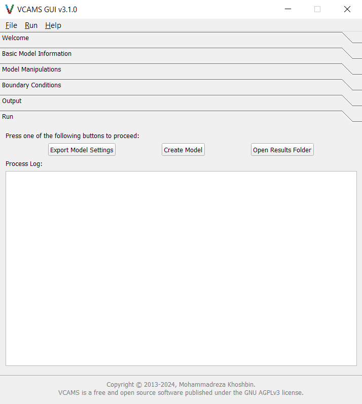
Fig. 37 The GUI’s “Run” tab for Example G-2.
After filling the form, the model can be created by pressing the “Create Model” button. The screen automatically switches to the Run tab and will show the program log.
At the end of the process, the dialog box shown in Fig. 38 announces the completion. Note that the path to the output file will be different depending on the input parameters and the machine.

Fig. 38 The GUI’s “Done!” dialog box that is shown after creation of the model in Example G-2.
Also, the program log and a summary of model information will be shown in the Process Log section of the Run tab. It will also be written to a .log file in the output folder.
Finally, a configuration file based on the examples will be written to the output folder
and can be used to import the model in the future.
It will look like this.